Monday, September 7, 2020

STM32F103R6 SPI Interfaces To A Single Seven-Segment Display

In this example I use the STM32F103R6 and its SPI1 to drive a single common cathode 7-Segment display using three wires - Serial Data, Serial Clock, and Enable pin. However the SPI communication could be create via user program. But in the STM32CubeIDE we can configure the hardware SPI easily using its code configuration wizard. After the code is created, the program just call a few function to transfer/receive the data.

STM32F103R6 SPI Interfaces To A Single Seven-Segment Display
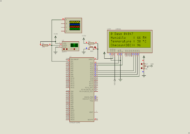
Simulating Program In Proteus

I place a push button connects to PA15. Whenever it's press, the controller sends the display data data between 0 and 9. 

STM32F103R6 SPI Interfaces To A Single Seven-Segment Display

SPI1 and Pin Configuration

I select my own Enable pin at PA8. It latch the data into the register at the high to low transition. I have a similar post that just use a bar-graph LED.

  1. /* USER CODE BEGIN Header */
  2. /**
  3.   ******************************************************************************
  4.   * @file : main.c
  5.   * @brief : Main program body
  6.   ******************************************************************************
  7.   * @attention
  8.   *
  9.   * <h2><center>&copy; Copyright (c) 2022 STMicroelectronics.
  10.   * All rights reserved.</center></h2>
  11.   *
  12.   * This software component is licensed by ST under BSD 3-Clause license,
  13.   * the "License"; You may not use this file except in compliance with the
  14.   * License. You may obtain a copy of the License at:
  15.   * opensource.org/licenses/BSD-3-Clause
  16.   *
  17.   ******************************************************************************
  18.   */
  19. /* USER CODE END Header */
  20. /* Includes ------------------------------------------------------------------*/
  21. #include "main.h"
  22.  
  23. /* Private variables ---------------------------------------------------------*/
  24. SPI_HandleTypeDef hspi1;
  25.  
  26. /* Private function prototypes -----------------------------------------------*/
  27. void SystemClock_Config(void);
  28. static void MX_GPIO_Init(void);
  29. static void MX_SPI1_Init(void);
  30. /* USER CODE BEGIN PFP */
  31.  
  32. /**
  33.   * @brief The application entry point.
  34.   * @retval int
  35.   */
  36. const unsigned char DisplayData[10]={0x3F,0x06,0x5B,0x4F,0x66,0x6D,0x7D,0x07,0x7F,0x6F};
  37. uint8_t txData=0;
  38. uint8_t rxData=0;
  39. uint8_t oldData=0xFF;
  40.  
  41. int main(void)
  42. {
  43. /* Reset of all peripherals, Initializes the Flash interface and the Systick. */
  44. HAL_Init();
  45.  
  46. /* Configure the system clock */
  47. SystemClock_Config();
  48.  
  49. /* Initialize all configured peripherals */
  50. MX_GPIO_Init();
  51. MX_SPI1_Init();
  52.  
  53. /* Infinite loop */
  54. /* USER CODE BEGIN WHILE */
  55. while (1)
  56. {
  57. if(HAL_GPIO_ReadPin(SW_GPIO_Port,SW_Pin)==0){
  58. HAL_Delay(200);
  59. txData+=1;
  60. }
  61. if(txData>9) txData=0;
  62. if(oldData!=txData){
  63. //HAL_SPI_Transmit(&hspi1, &txData, 1, 10);
  64. HAL_SPI_Transmit(&hspi1,&DisplayData[txData],1,10);
  65. HAL_GPIO_WritePin(EN_GPIO_Port,EN_Pin,GPIO_PIN_SET);
  66. HAL_GPIO_WritePin(EN_GPIO_Port,EN_Pin,GPIO_PIN_RESET);
  67. oldData=txData;
  68. }
  69. }
  70. }
  71.  
  72. /**
  73.   * @brief System Clock Configuration
  74.   * @retval None
  75.   */
  76. void SystemClock_Config(void)
  77. {
  78. RCC_OscInitTypeDef RCC_OscInitStruct = {0};
  79. RCC_ClkInitTypeDef RCC_ClkInitStruct = {0};
  80.  
  81. /** Initializes the RCC Oscillators according to the specified parameters
  82.   * in the RCC_OscInitTypeDef structure.
  83.   */
  84. RCC_OscInitStruct.OscillatorType = RCC_OSCILLATORTYPE_HSI;
  85. RCC_OscInitStruct.HSIState = RCC_HSI_ON;
  86. RCC_OscInitStruct.HSICalibrationValue = RCC_HSICALIBRATION_DEFAULT;
  87. RCC_OscInitStruct.PLL.PLLState = RCC_PLL_NONE;
  88. if (HAL_RCC_OscConfig(&RCC_OscInitStruct) != HAL_OK)
  89. {
  90. Error_Handler();
  91. }
  92. /** Initializes the CPU, AHB and APB buses clocks
  93.   */
  94. RCC_ClkInitStruct.ClockType = RCC_CLOCKTYPE_HCLK|RCC_CLOCKTYPE_SYSCLK
  95. |RCC_CLOCKTYPE_PCLK1|RCC_CLOCKTYPE_PCLK2;
  96. RCC_ClkInitStruct.SYSCLKSource = RCC_SYSCLKSOURCE_HSI;
  97. RCC_ClkInitStruct.AHBCLKDivider = RCC_SYSCLK_DIV1;
  98. RCC_ClkInitStruct.APB1CLKDivider = RCC_HCLK_DIV1;
  99. RCC_ClkInitStruct.APB2CLKDivider = RCC_HCLK_DIV1;
  100.  
  101. if (HAL_RCC_ClockConfig(&RCC_ClkInitStruct, FLASH_LATENCY_0) != HAL_OK)
  102. {
  103. Error_Handler();
  104. }
  105. }
  106.  
  107. /**
  108.   * @brief SPI1 Initialization Function
  109.   * @param None
  110.   * @retval None
  111.   */
  112. static void MX_SPI1_Init(void)
  113. {
  114.  
  115. /* USER CODE BEGIN SPI1_Init 0 */
  116.  
  117. /* USER CODE END SPI1_Init 0 */
  118.  
  119. /* USER CODE BEGIN SPI1_Init 1 */
  120.  
  121. /* USER CODE END SPI1_Init 1 */
  122. /* SPI1 parameter configuration*/
  123. hspi1.Instance = SPI1;
  124. hspi1.Init.Mode = SPI_MODE_MASTER;
  125. hspi1.Init.Direction = SPI_DIRECTION_1LINE;
  126. hspi1.Init.DataSize = SPI_DATASIZE_8BIT;
  127. hspi1.Init.CLKPolarity = SPI_POLARITY_LOW;
  128. hspi1.Init.CLKPhase = SPI_PHASE_1EDGE;
  129. hspi1.Init.NSS = SPI_NSS_SOFT;
  130. hspi1.Init.BaudRatePrescaler = SPI_BAUDRATEPRESCALER_2;
  131. hspi1.Init.FirstBit = SPI_FIRSTBIT_MSB;
  132. hspi1.Init.TIMode = SPI_TIMODE_DISABLE;
  133. hspi1.Init.CRCCalculation = SPI_CRCCALCULATION_DISABLE;
  134. hspi1.Init.CRCPolynomial = 10;
  135. if (HAL_SPI_Init(&hspi1) != HAL_OK)
  136. {
  137. Error_Handler();
  138. }
  139. /* USER CODE BEGIN SPI1_Init 2 */
  140.  
  141. /* USER CODE END SPI1_Init 2 */
  142.  
  143. }
  144.  
  145. /**
  146.   * @brief GPIO Initialization Function
  147.   * @param None
  148.   * @retval None
  149.   */
  150. static void MX_GPIO_Init(void)
  151. {
  152. GPIO_InitTypeDef GPIO_InitStruct = {0};
  153.  
  154. /* GPIO Ports Clock Enable */
  155. __HAL_RCC_GPIOA_CLK_ENABLE();
  156.  
  157. /*Configure GPIO pin Output Level */
  158. HAL_GPIO_WritePin(EN_GPIO_Port, EN_Pin, GPIO_PIN_RESET);
  159.  
  160. /*Configure GPIO pin : EN_Pin */
  161. GPIO_InitStruct.Pin = EN_Pin;
  162. GPIO_InitStruct.Mode = GPIO_MODE_OUTPUT_PP;
  163. GPIO_InitStruct.Pull = GPIO_NOPULL;
  164. GPIO_InitStruct.Speed = GPIO_SPEED_FREQ_LOW;
  165. HAL_GPIO_Init(EN_GPIO_Port, &GPIO_InitStruct);
  166.  
  167. /*Configure GPIO pin : SW_Pin */
  168. GPIO_InitStruct.Pin = SW_Pin;
  169. GPIO_InitStruct.Mode = GPIO_MODE_INPUT;
  170. GPIO_InitStruct.Pull = GPIO_PULLUP;
  171. HAL_GPIO_Init(SW_GPIO_Port, &GPIO_InitStruct);
  172.  
  173. }
  174.  
  175. /**
  176.   * @brief This function is executed in case of error occurrence.
  177.   * @retval None
  178.   */
  179. void Error_Handler(void)
  180. {
  181. /* USER CODE BEGIN Error_Handler_Debug */
  182. /* User can add his own implementation to report the HAL error return state */
  183. __disable_irq();
  184. while (1)
  185. {
  186. }
  187. }
  188.  
  189. #ifdef USE_FULL_ASSERT
  190. /**
  191.   * @brief Reports the name of the source file and the source line number
  192.   * where the assert_param error has occurred.
  193.   * @param file: pointer to the source file name
  194.   * @param line: assert_param error line source number
  195.   * @retval None
  196.   */
  197. void assert_failed(uint8_t *file, uint32_t line)
  198. {
  199. /* USER CODE BEGIN 6 */
  200. /* User can add his own implementation to report the file name and line number,
  201.   ex: printf("Wrong parameters value: file %s on line %d\r\n", file, line) */
  202. /* USER CODE END 6 */
  203. }
  204. #endif /* USE_FULL_ASSERT */
  205.  
  206. /************************ (C) COPYRIGHT STMicroelectronics *****END OF FILE****/
  207.  

Click here to download its source file.

For other similar posts please check,

  1. Getting Started With STM32F103C8T6 Module with STM32CubeIDE
  2.  STM32F103C8T6 Blue Pill SysTick and Multiplexing Display Example
  3.  STM32F103C8T6 Blue Pill Switch And Multiplexing Display Interface Using SysTick
  4.  STM32F103C8T6 Blue Pill SysTick LED Blinking
  5. STM32F103R6 Common Anode Seven Segments Display Example 
  6. STM32F103R6 Common Anode Seven Segments Display And Switch Interfacing 
  7. STM32F103R6 Simple 2-Digit Multiplexing Display And Switch Example 
  8. STM32F103R6 SysTick And Digital Clock Example 
  9. STM32F103R6 SysTick Two-Digit Multiplexing Display and Push Button
  10. LED Blinking With STM32F103R6 Using SysTick 
  11. STM32F103R6 SPI Interfaces To SN74HC595N Shift Registers 
  12. STM32F103R6 GPIO Interfaces To A Character LCD In 8-Bit Mode 
  13. STM32F103R6 SPI Interfaces To A Single Seven-Segment Display 
  14. STM32F103R6 Interfaces To A Character LCD Using MikroC For ARM


No comments:

Post a Comment